Getting Started
These are the initial steps required to be completed before a new 3D probe can be used regularly.
1. Install Carvera Community Software
reset switch to using the Community Controller. This is a known communications compatibility limitation
.The Community Firmware
and Controller
is required to use the 3D probe. The easiest way to confirm that you are running the Community firmware is to run the MDI command
version and ensure the version response contains the character “c” denoting that it is a Community firmware. eg: 2.1.0c

2. Connect the probe
Open the Community Controller, connect to the machine, change the tool in the collet to the 3D Probe, and plug the probe into the probe port.
Users of the CA1 will be familiar for how to manually load tools. How-to video .
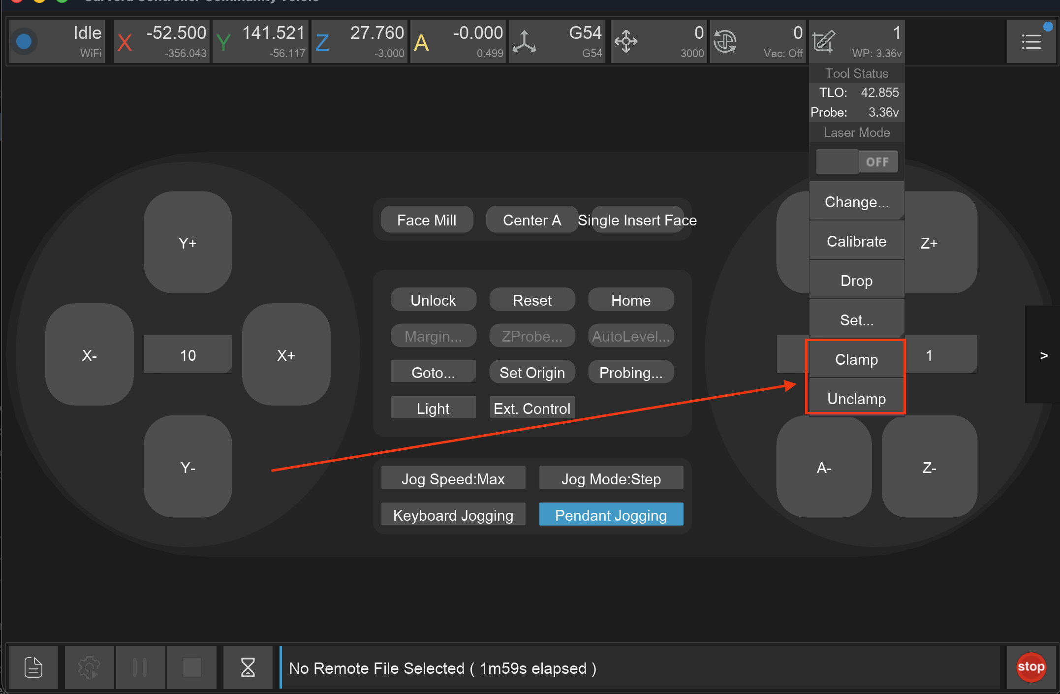
Users of the C1 will need to drop other tools and unclamp/clamp the collet to manually load a tool not in the tool rack. This can be done using the Controller buttons  and
and  (found in the TOOL status-bar dropdown
).
(found in the TOOL status-bar dropdown
).
Hold the probe in the collet until the machine has clamped it.
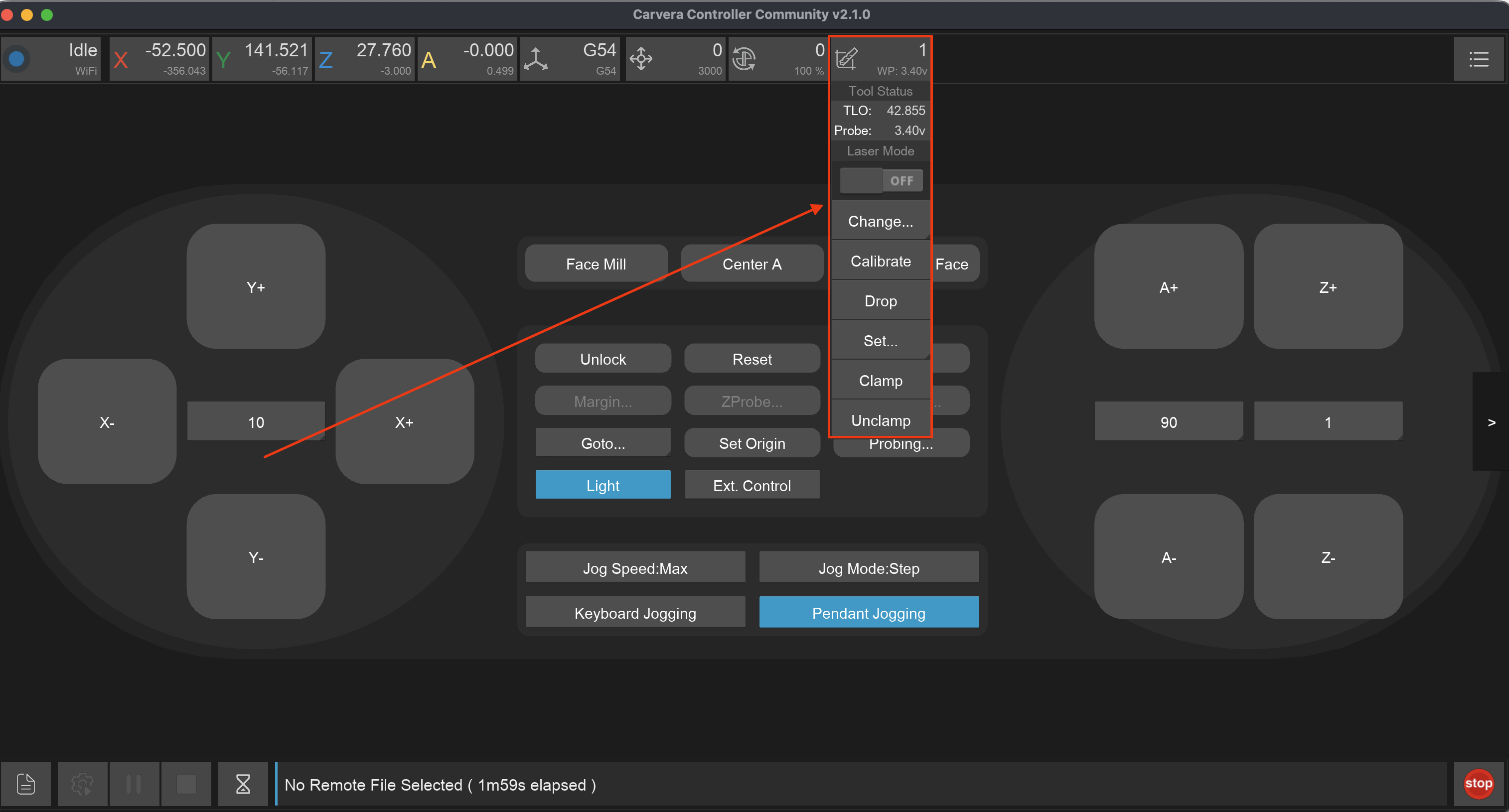
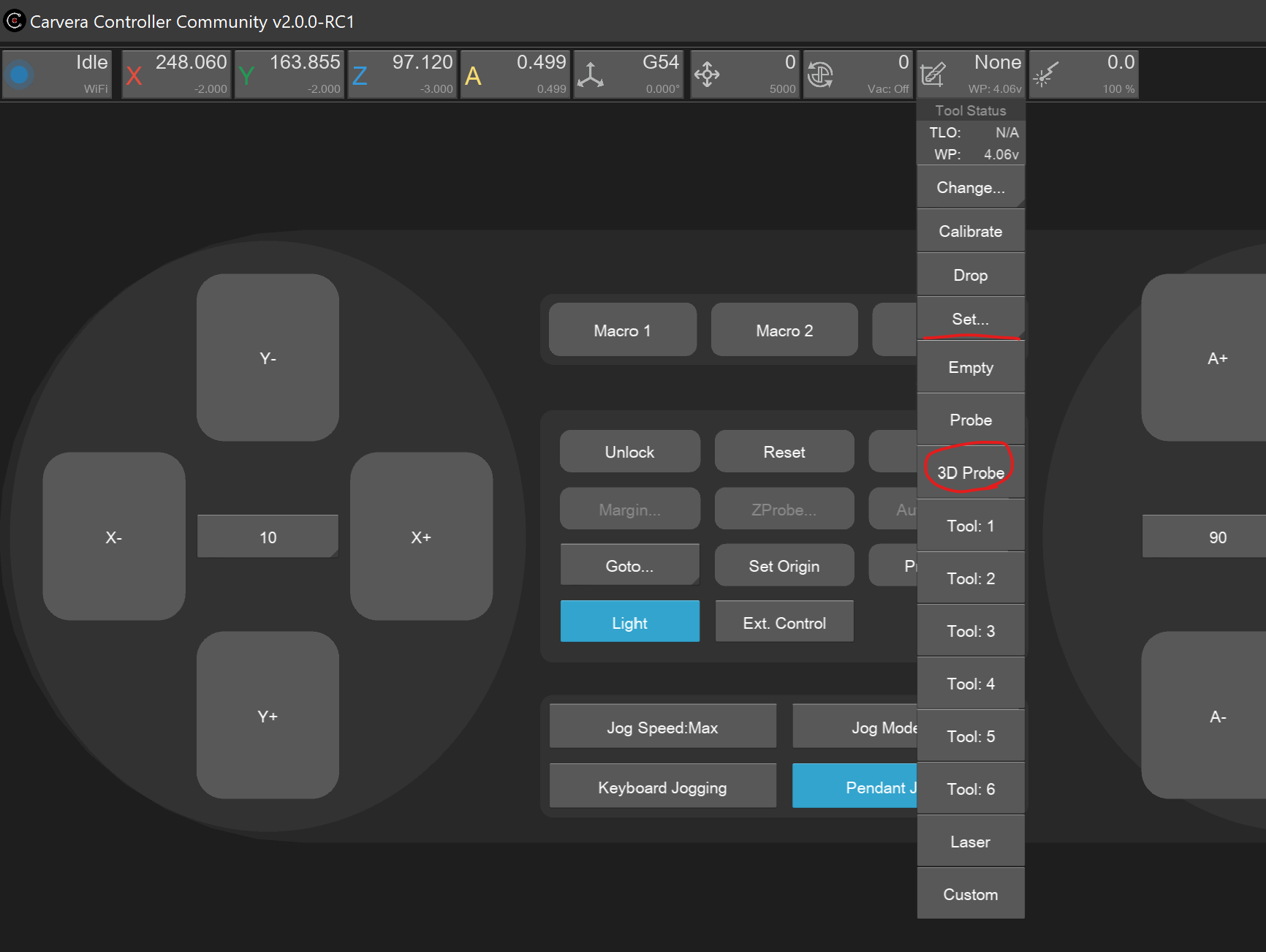
Using the Controller, use the TOOL dropdown menu to set the current tool to 3D Probe.
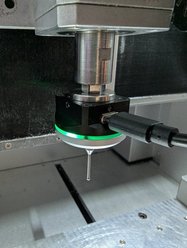
The probe should now have a green LED that shines through the clear plastic in the probe body.
3. Test the probe
It’s important to test that the machine registers when the probe is triggered. The Community firmware has 3D Probe Crash Protection which will halt the machine if the probe is activated while the spindle is moving and a probe macro is not being executed. This will help protect the probe stylus from damage from unexpected collisions, however this functionality requires the machine correctly receive the signal that the probe has been triggered.
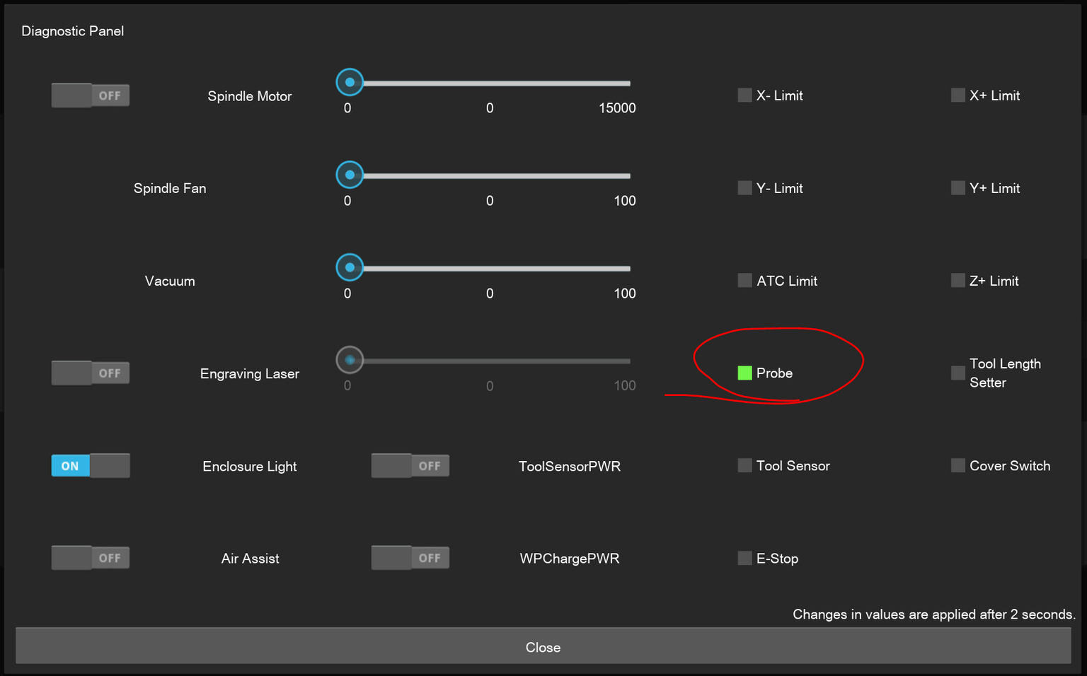
You can test that the machine is receiving probe trigger signals by lightly pressing the probe tip with your hand. On the probe the green led will change to red when it is triggered. In the Diagnostic panel of the Controller, the Probe input should be lit green when the probe is triggered.
4. Set Probe Config Setting
Included with the probe is a card that provides specific calibration details about your probe. On the card an effective probe tip diameter should be provided, open the MDI terminal
run the below command replacing the value 1.700 with the value written on the card:
config-set sd zprobe.probe_tip_diameter 1.700
Now run reset to apply the setting.
reset command you need to disconnect the USB cable afterwards. Unfortunately the design of the control board allows the microprocessor to continue being powered by the USB connection, preventing resets from completing.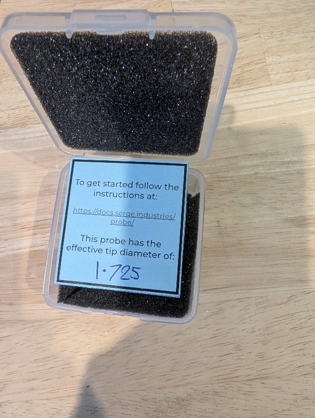
5. Set a TLO correction value
Some Probes shipped from May 2026 onward may use a revised spring in the mechanism. Probing accuracy is unchanged, but the new spring’s force is close to that of the Tool Length Offset (TLO) sensor, so TLO readings may be off by a fraction of a millimetre, and raise an error. You can correct for this in firmware.
First determine if your probe is affected. This is easy to do. Run a TLO calibration by selecting the  option from the TOOL dropdown menu
. If this probe is affected, the TLO probing will raise an alarm with the error message:
option from the TOOL dropdown menu
. If this probe is affected, the TLO probing will raise an alarm with the error message:
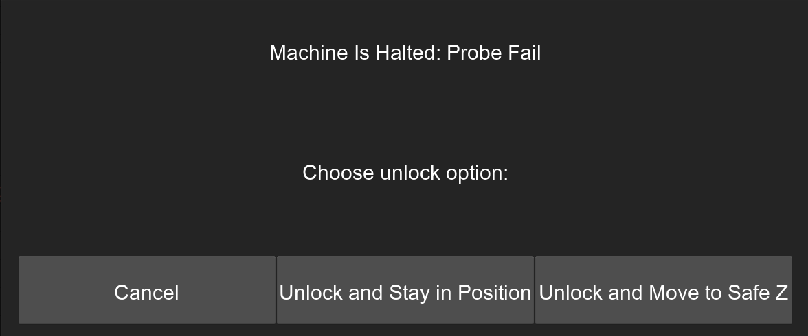
If you don’t get this error, you don’t need to worry. You are now ready to use the probe !
If you get this error open the MDI terminal, you will see more detail include the text: ALARM: Probe failed to trigger within safety margin (0.1mm).
On most of the probes that are affected by this issue, the TLO reading is incorrect by around 0.4mm. You can apply the fix by executing the following commands in the MDI:
config-set sd zprobe.calibration_safety_margin 1
config-set sd zprobe.three_axis_probe_tlo_correction 0.4
reset
After applying these settings, you are now ready to use the probe !
If you want to measure the exact TLO error offset and correct for it, it’s possible to get the Z probing accuracy down to 0.03mm. Follow the TLO adjustment procedure .