TLO correction procedure
Probes shipped from May 2026 onward may use a revised spring in the mechanism. Probing accuracy is unchanged, but the new spring’s force is close to that of the Tool Length Offset (TLO) sensor, so TLO readings may be off by a fraction of a millimetre, and raise an error. You can correct for this in firmware.
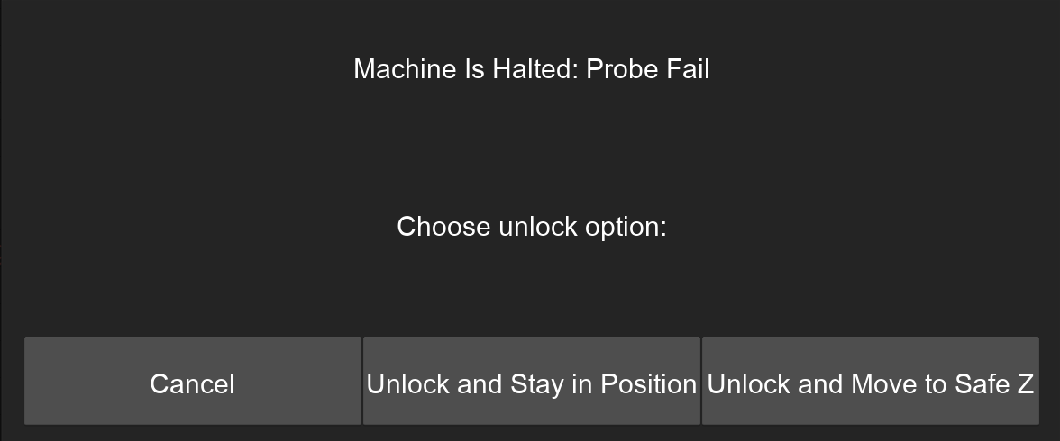
First determine if your probe is affected. This is easy to do. Run a TLO calibration by selecting the 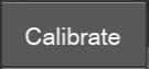 option from the TOOL dropdown menu
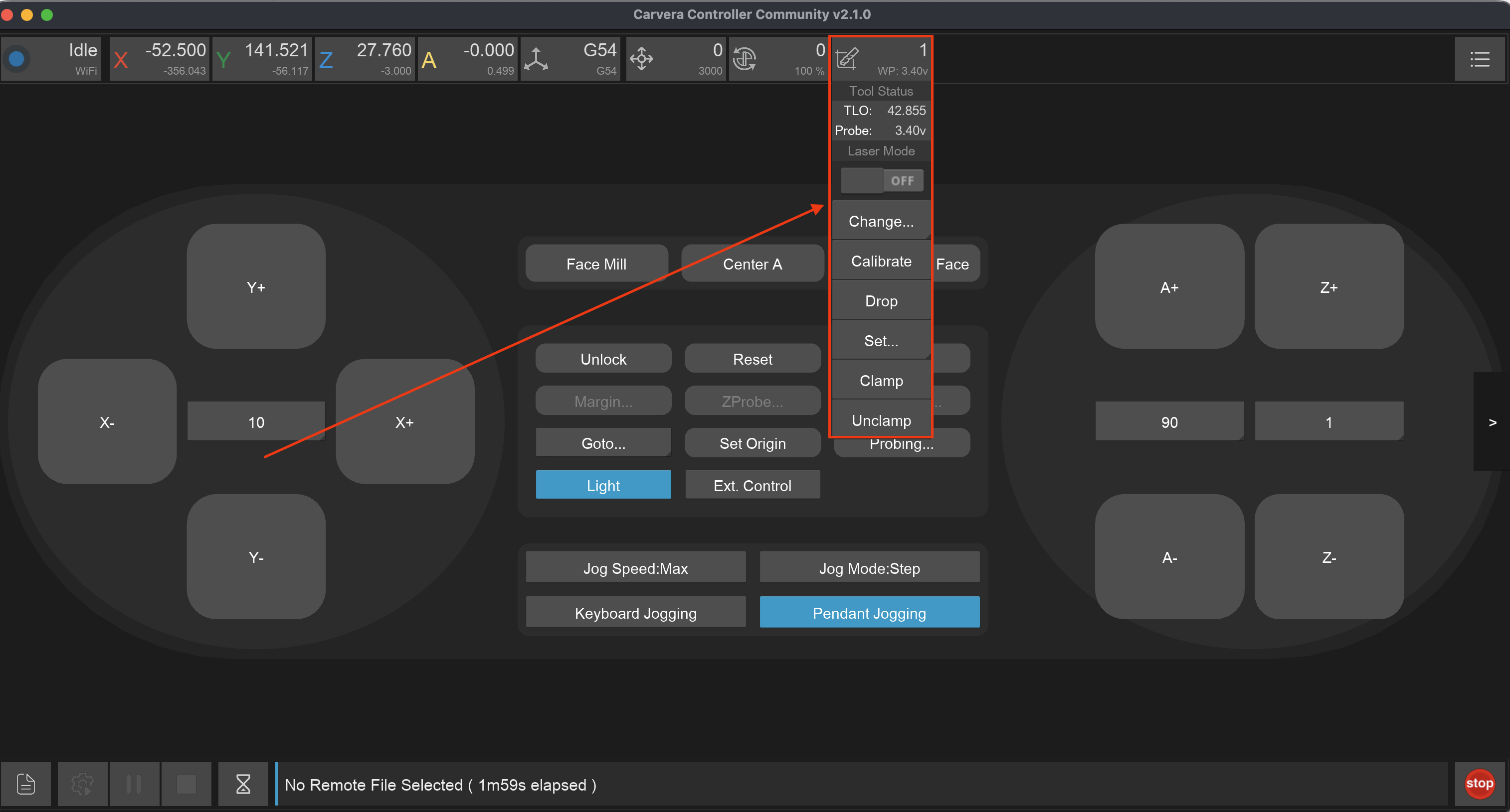
. If this probe is affected, the TLO probing will raise an alarm with the error message:
option from the TOOL dropdown menu
. If this probe is affected, the TLO probing will raise an alarm with the error message:
If you don’t get this error, you this probe is unaffected and you don’t need to perform this procedure.
If you get this error open the MDI terminal, you will see more detail include the text: ALARM: Probe failed to trigger within safety margin (0.1mm).
What this is referring to is the distance the machine had to move once after triggering the TLO sensor until it also triggered the probe. The machine firmware captures both values so that it can automatically compensates for the distance required to trigger the probe in the downwards direction. However if this difference is above 0.1mm the compensation isn’t as effective, and additional TLO correction should be used. The config key for additional correction is zprobe.three_axis_probe_tlo_correction.
Procedure
You can determine the value to use for zprobe.three_axis_probe_tlo_correction by doing a Z axis probe of the same point on the bed with both the stock and 3D probes, and finding the difference between. Follow this procedure to do that:
First Open the MDI and execute the following command:
config-set sd zprobe.calibration_safety_margin 1, then theresetcommand to apply it. This will increase the safety margin to 1mm.Change back to the original probe included with the machine. Perform a TLO
Jog the spindle to a flat part of the bed (for example anchor2 using the command
M496.4), and runM466 Z-200 S0to probe the Z location of the spot.Switch to the 3D Probe, perform a TLO calibrate, and probe the same spot (use the same command)
Compare the difference between the two Work Coordinates in the MDI. Set this as the correction
via config-set sd zprobe.three_axis_probe_tlo_correction <value>and runresetto apply the setting.To test re-run the TLO calibration on the 3D probe, and re-probe the same spot. The Work Coordinates should now be within 0.05mm of the stock probe.
Here is a worked example:
; Step 1. Increase the safety margin
config-set sd zprobe.calibration_safety_margin 1
reset

; Is this probe affected by the increased spring force?
; Run TLO calibration
M491
...
Probe trigger offset: -0.425mm (probe Z:-70.375, cal Z:-69.950)
...
; Yes! We need to determine how much tlo correction needs to be applied

; Step 2. Switch back to stock probe and tlo calibrate
M493.2T0
M491

; Step 3. Move to anchor 2 location and run probe in Z axis
M496.4
M466 Z-200 S0
ok
Probing Single Axis
--- Machine Coordinates ---
Final Positon Z: -111.000
--- Work Coordinates ---
Final Positon Z: -58.930

; Step 4. Switch back to 3D probe, tlo calibrate, and probe the same spot
M493.2T999990
M491
M496.4
M466 Z-200 S0
--- Machine Coordinates ---
Final Positon Z: -111.385
--- Work Coordinates ---
Final Positon Z: -58.530

; Step 5. 3D Probe Z - Stock Probe Z = Correction value
; (-58.530) - (-58.930) = 0.4mm of correction is required
config-set sd zprobe.three_axis_probe_tlo_correction 0.4
reset


; Step 6. Re-calibrate TLO and Re-probe spot to verify correction.
M491
M496.4
M466 Z-200 S0
ok
Probing Single Axis
--- Machine Coordinates ---
Final Positon Z: -111.385
--- Work Coordinates ---
Final Positon Z: -58.920

; And Work Coordinate is now within 0.01mm, success!