Usage
Basics
Regular usage of the probe involves the following steps:
- Load the Probe into the spindle collet
Users of the CA1 will be familiar for how to manually load tools. How-to video .
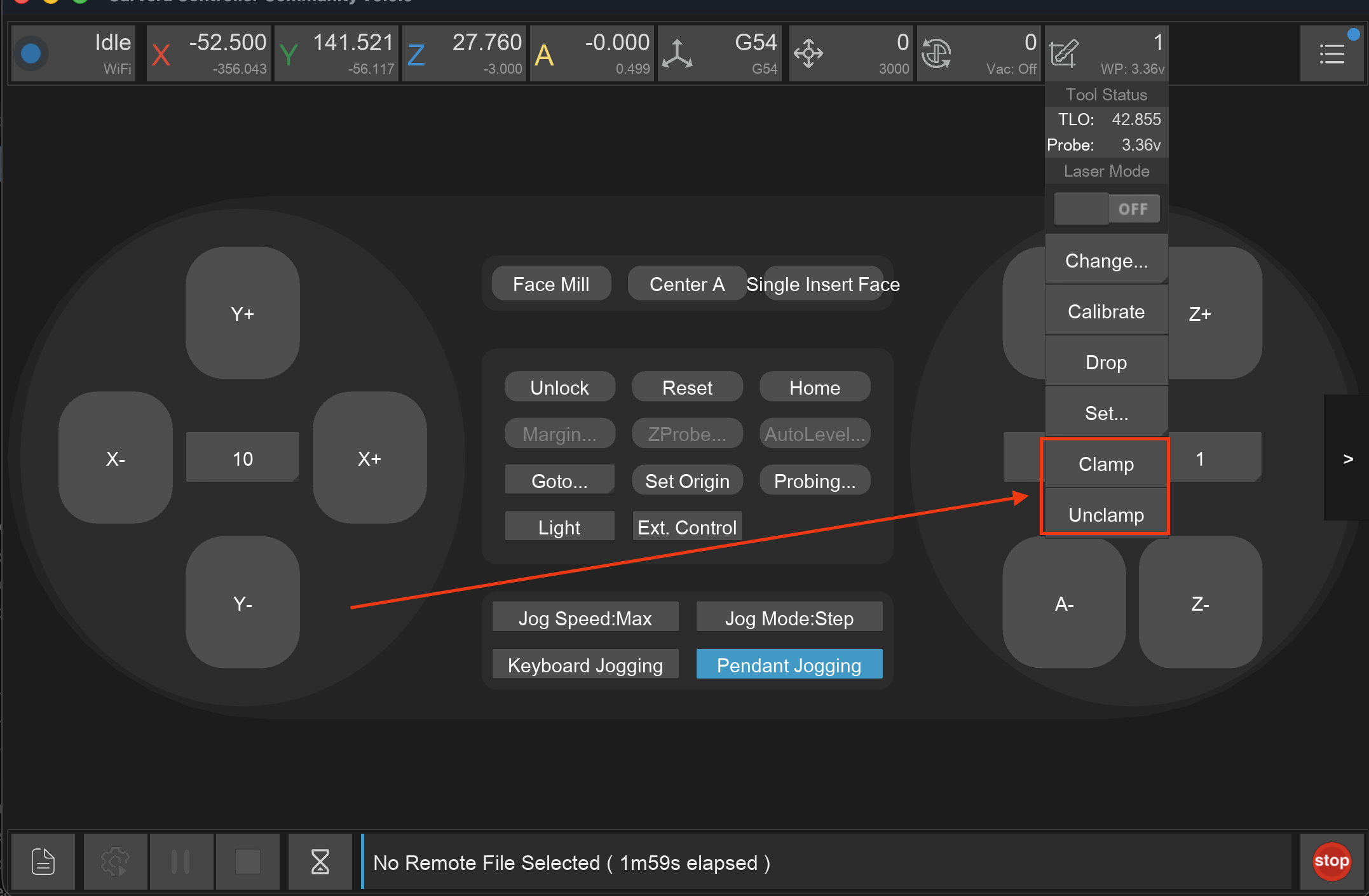
Users of the C1 will need to drop other tools and Unclamp/Clamp the collet to manually load a tool not in the tool rack. This can be done using the Controller buttons  and
and  (found in the TOOL dropdown menu
).
(found in the TOOL dropdown menu
).
Hold the probe in the collet until the machine has clamped it.
Set the current tool to Probe
By setting/changing the tool to 3D Probe in the Controller or by running the command
M6 T999990in the MDI.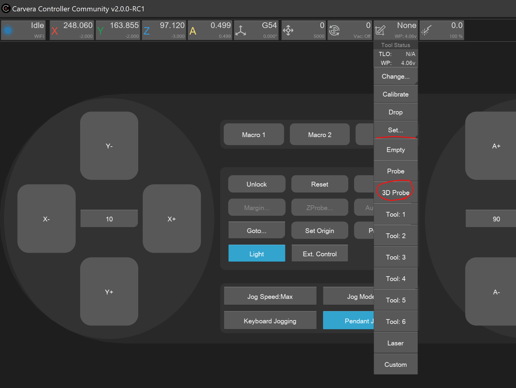
Set 3D Probe Calibrate the TLO
For Z probing to be accurate the machine needs to perform a TLO calibration. This can be triggered via the ATC status-bar drop down option
 or by running the MDI command
 M491.Ready to use Probing Commands
Now the probe can be used in the Controller or MDI.
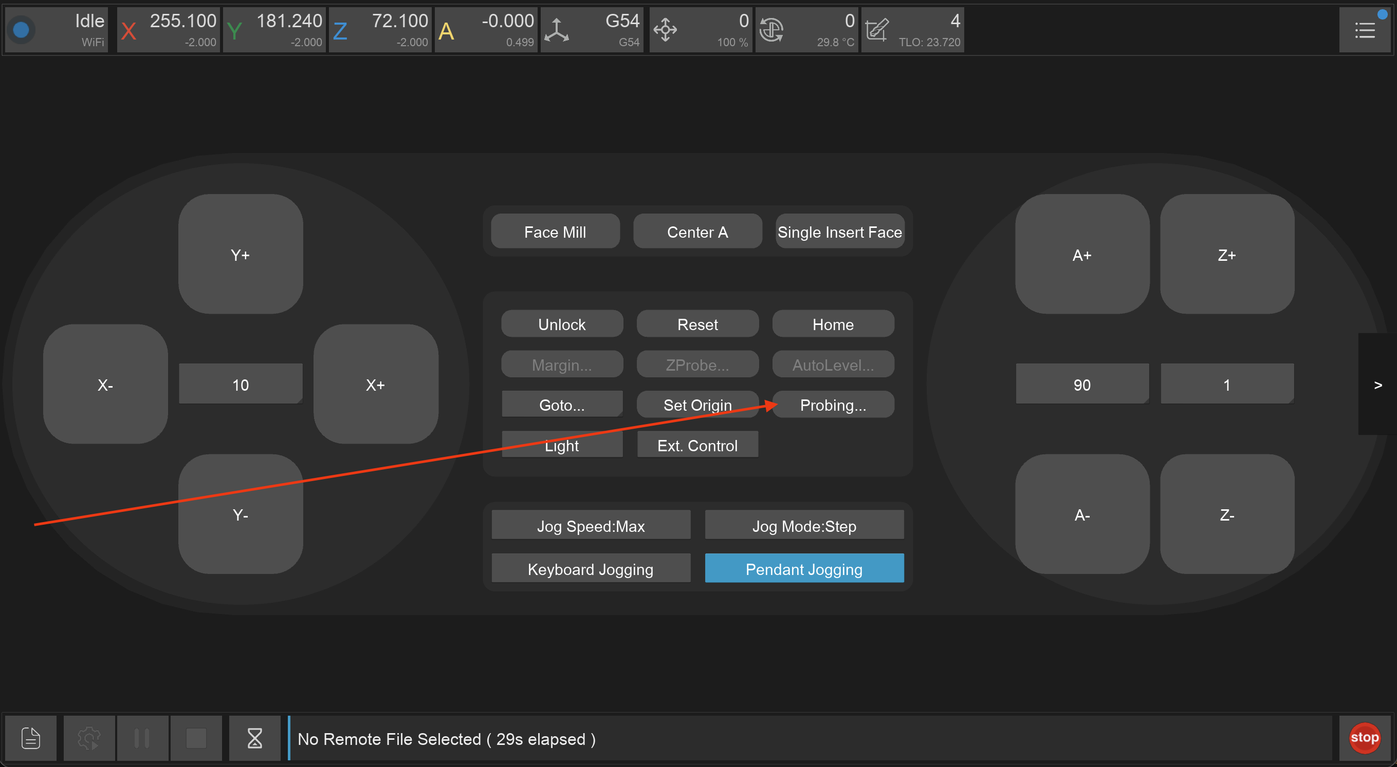
Probe Button Control Panel 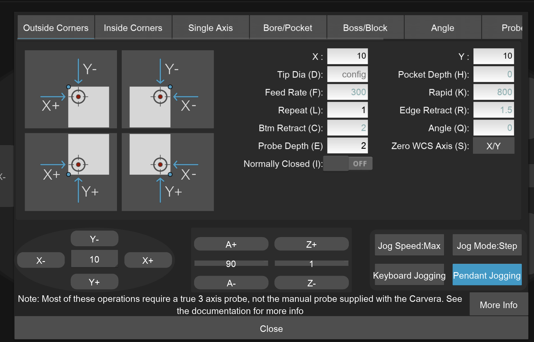
Probe UI
Probe UI Explanation
The Probe UI has 4 main sections:
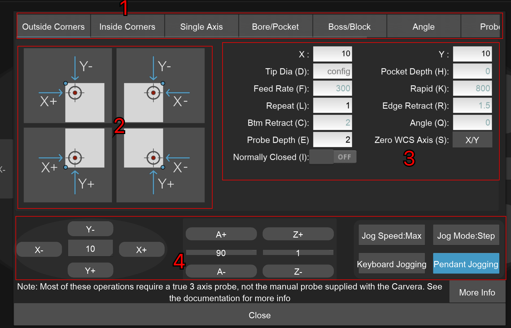
Different probing types grouped by category. Note that this is a horizontal scroll bar.
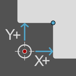
Type MCode Note Outside corner M464 Finds outside corner locations Inside corner M463 Inside corner locations Single axis M466 X, Y, and/or Z touch-off Bore / pocket M461 Inside circular or rectangular features Boss / Block M462 Outside bosses and blocks Axis angle M465 Angle for WCS rotation when used with that option Calibration M469.1-5 Measures and suggests machine calibration changes to offsets for anchor 1, anchor 2, A-axis headstock, A-axis height (4th axis) Probe tip M460.1 Measures the effective tip diameter on the probe 4th axis — stock leveling M465.1 Angular alignment of A-axis stock (Controller 4th axis probing section) Buttons for the different probe variations within the category. When selecting a probing operation in the controller the graphics have a set up standard:
The probe start position is always denoted by a red dot, usually surrounded by a crosshair
The final desired probe position is denoted by a blue dot if it is different than the starting crosshair
Probing moves are denoted in bright blue with arrows
Coloured green, red, or dark blue lines denote dimension lines
Inner corner probe example Probing Parameters. Default values are displayed in grey, If you mouse over the input box a tooltip will appear with more details. Note You likely want to use the results of the probe to set the Work Coordinate System Origin. This is the Zero WCS (S) parameter. The letters in the brackets are the parameter keys used in the command sent to the machine. Read the firmware documentation for more details.
Spindle jogging control buttons
Example Videos
The following are community videos showing how they use the probe: