Installation
0. Pre-requisites
The following is required to install the High Capacity Tool Rack:
- The Community Firmware and Controller Version 2.1.0 or above.
- 4mm allen key wrench
- 2.5mm allen key wrench
- 2mm allen key wrench
- 3D Touch probe - Strongly recommended, see step 7
Installation of the tool rack requires approximately 1 hour.
1. Remove Bed and Original Tool Rack
Installation of the new tool rack requires removing the bed to transfer the Wireless Probe and Tool Setter to the new rack.
- Remove any tools and wireless probe in the original rack slots, and clear the bed.
- Jog the spindle over to the left hand side so it’s not in the way of working on the tool rack.
- Power off the machine
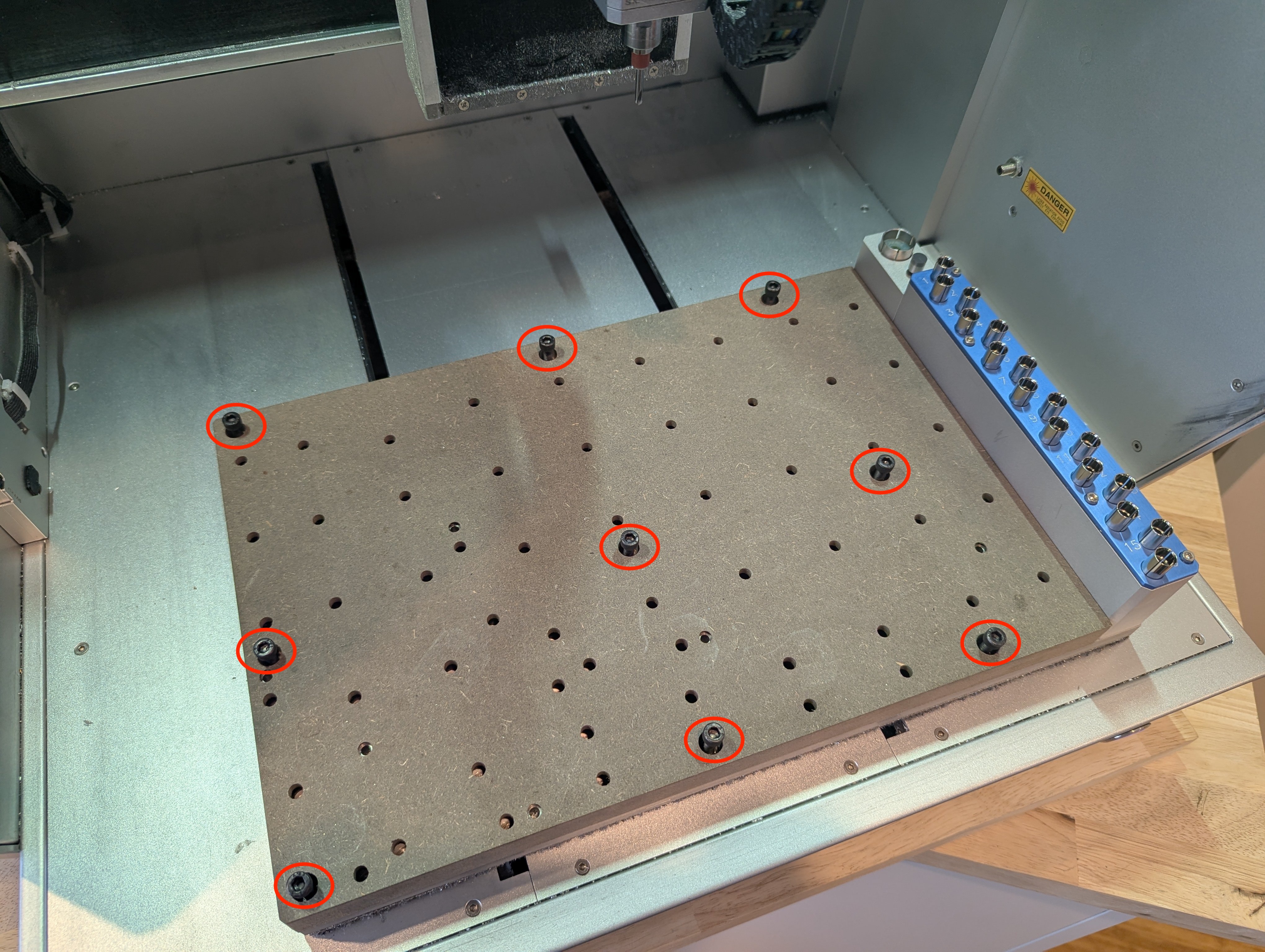
- Use a 4mm allen key to remove the 9 bolts holding the bed
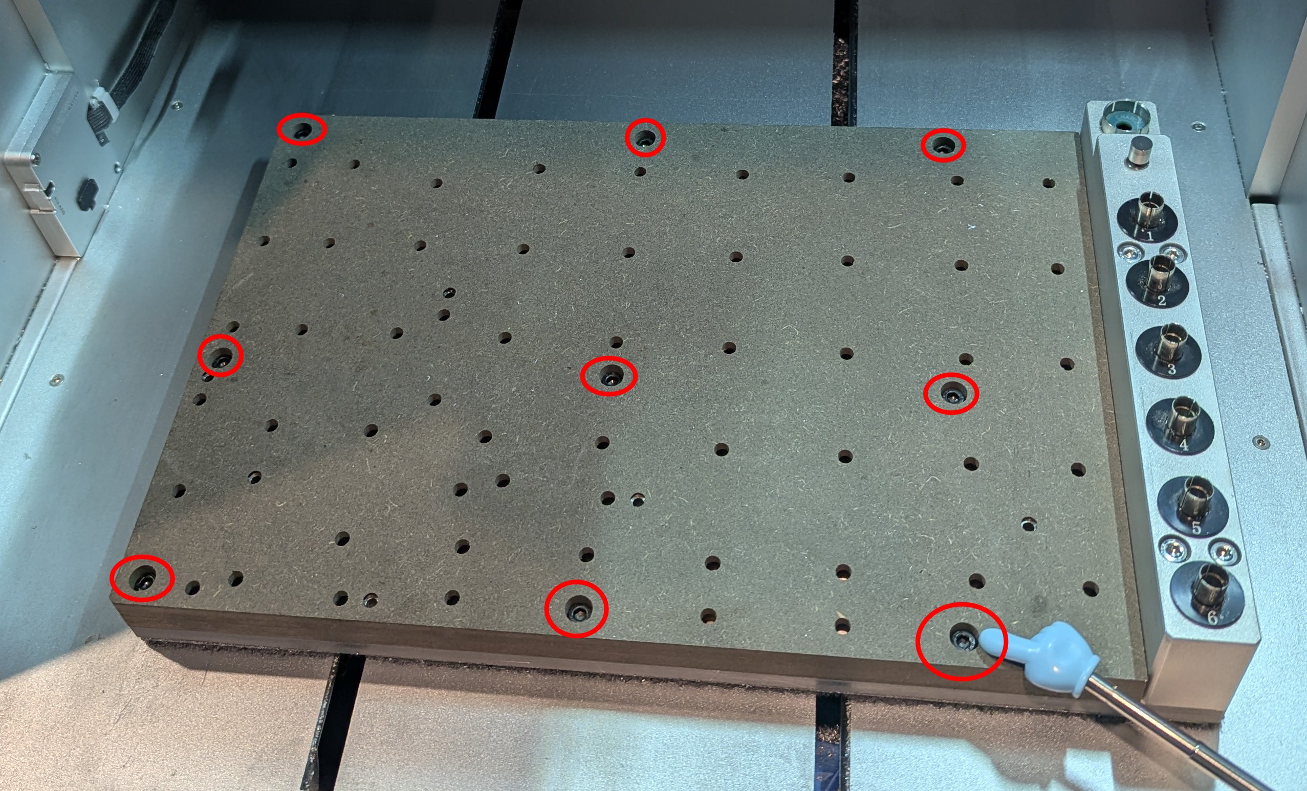
9 bolts holding the stock bed that need to be removed - Now carefully lift the bed up and off the carrier
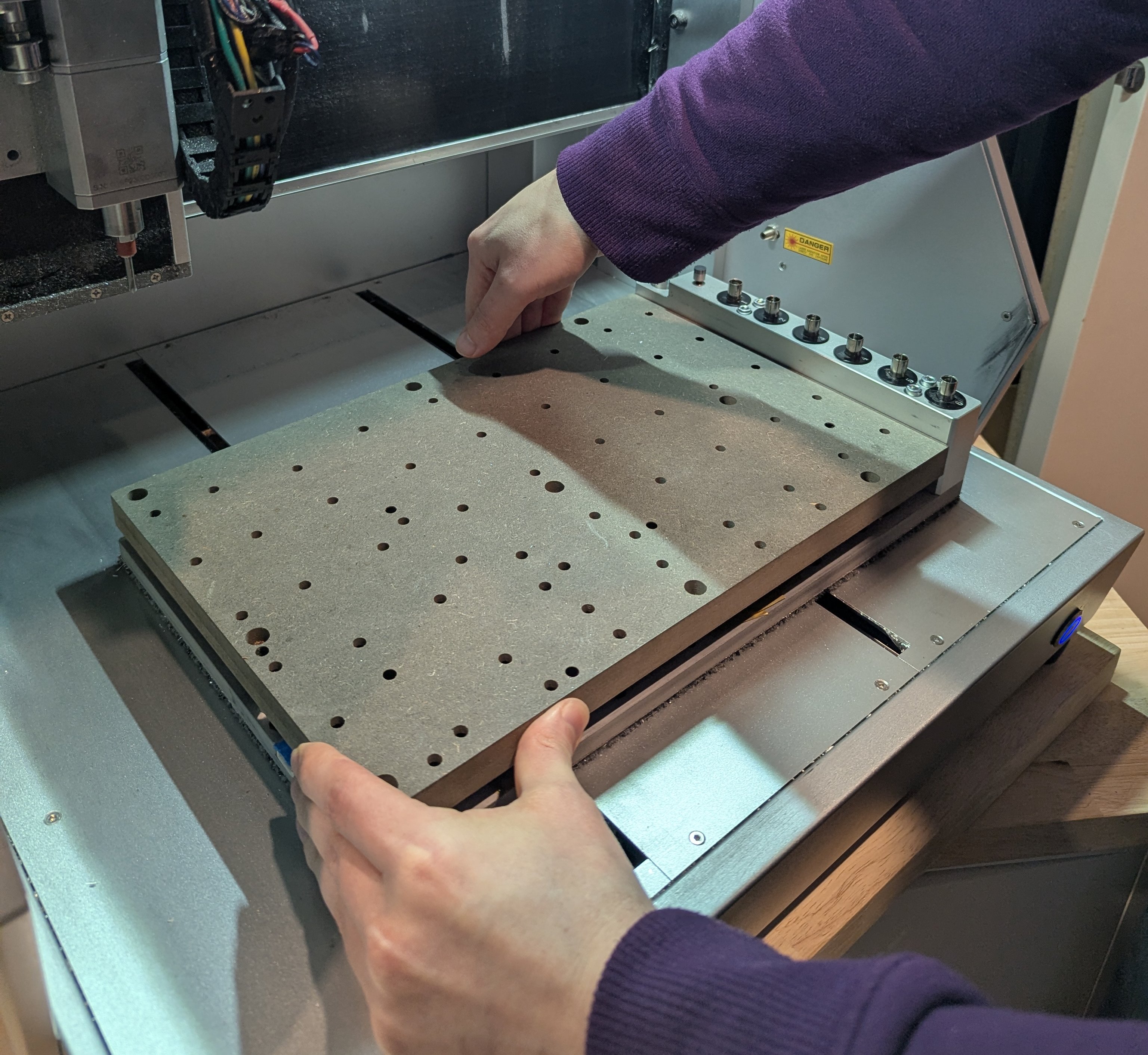
Remove the bed
2. Disconnect and Remove Original Tool Rack
- Disconnect the wireless probe and tool setter connectors from the upper pcb board on the bed carrier
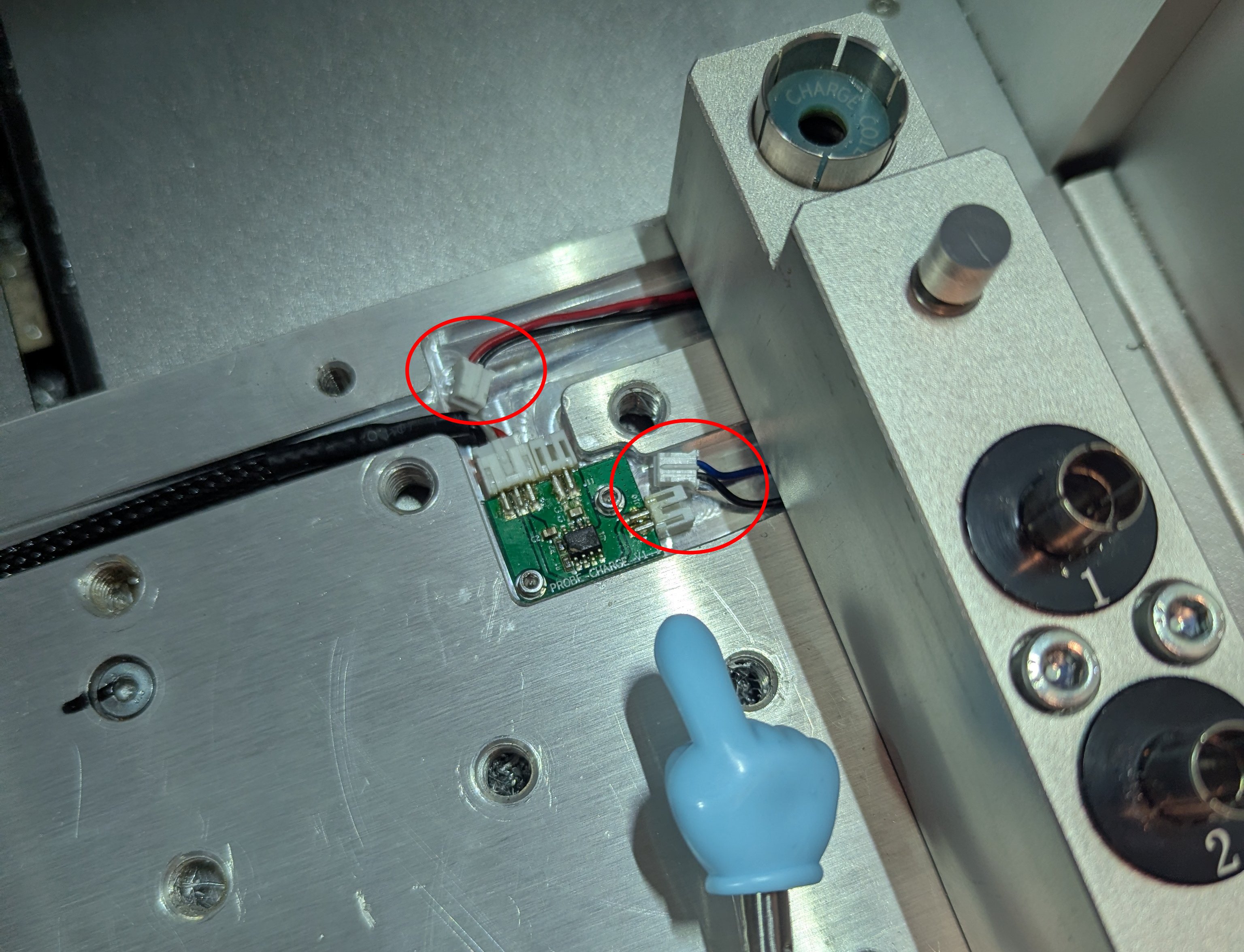
Disconnect the red/black and blue/black connectors - Use a 4mm allen key to remove the 4 bolts holding the original tool rack
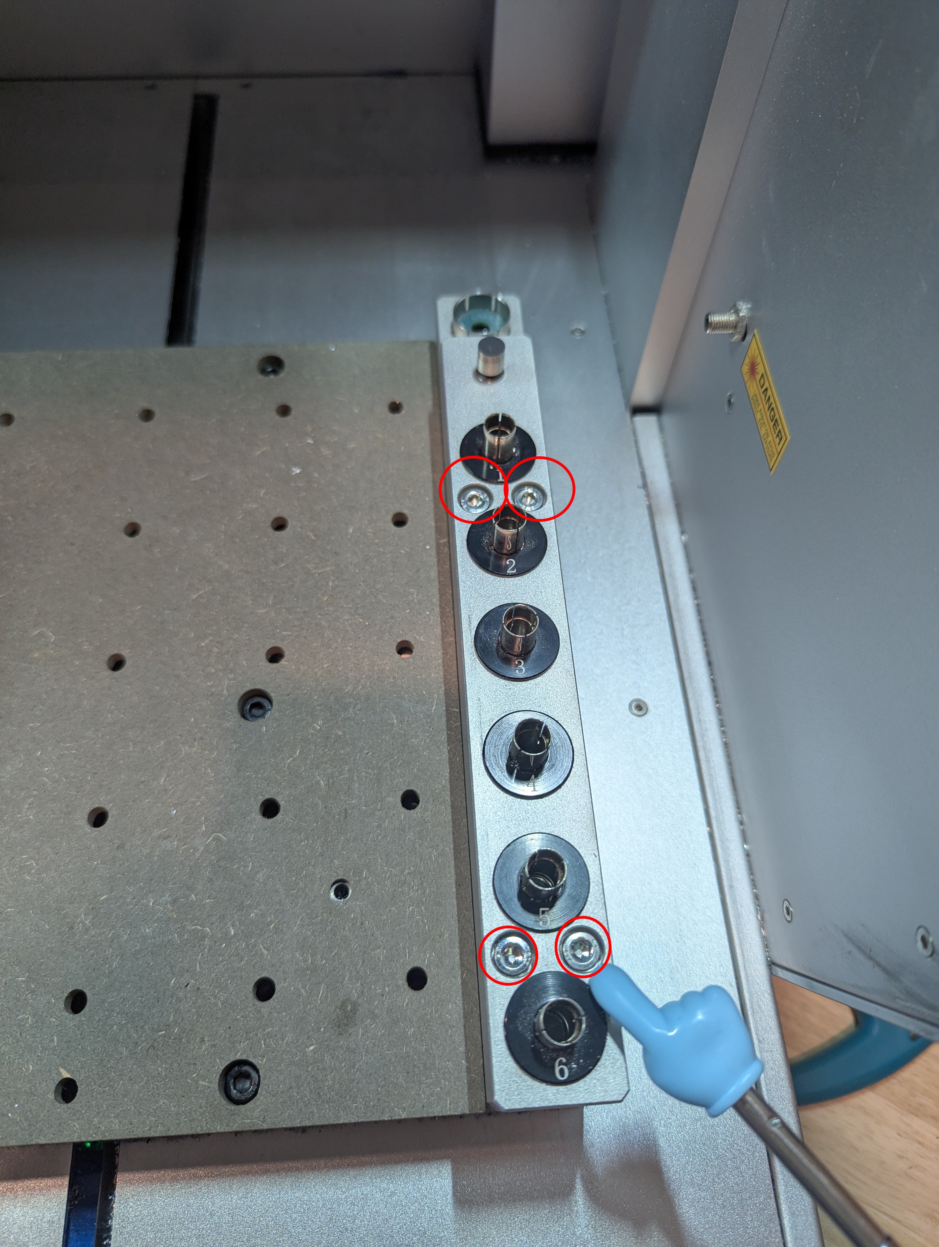
4 bolts holding tool rack need to be removed - With both hands pull the original rack off the carrier. Note that the rack has two alignment pins which can make removing it difficult if you don’t pull it upward evenly on both sides. If stuck, it can help to rock it side to side a little to loosen.
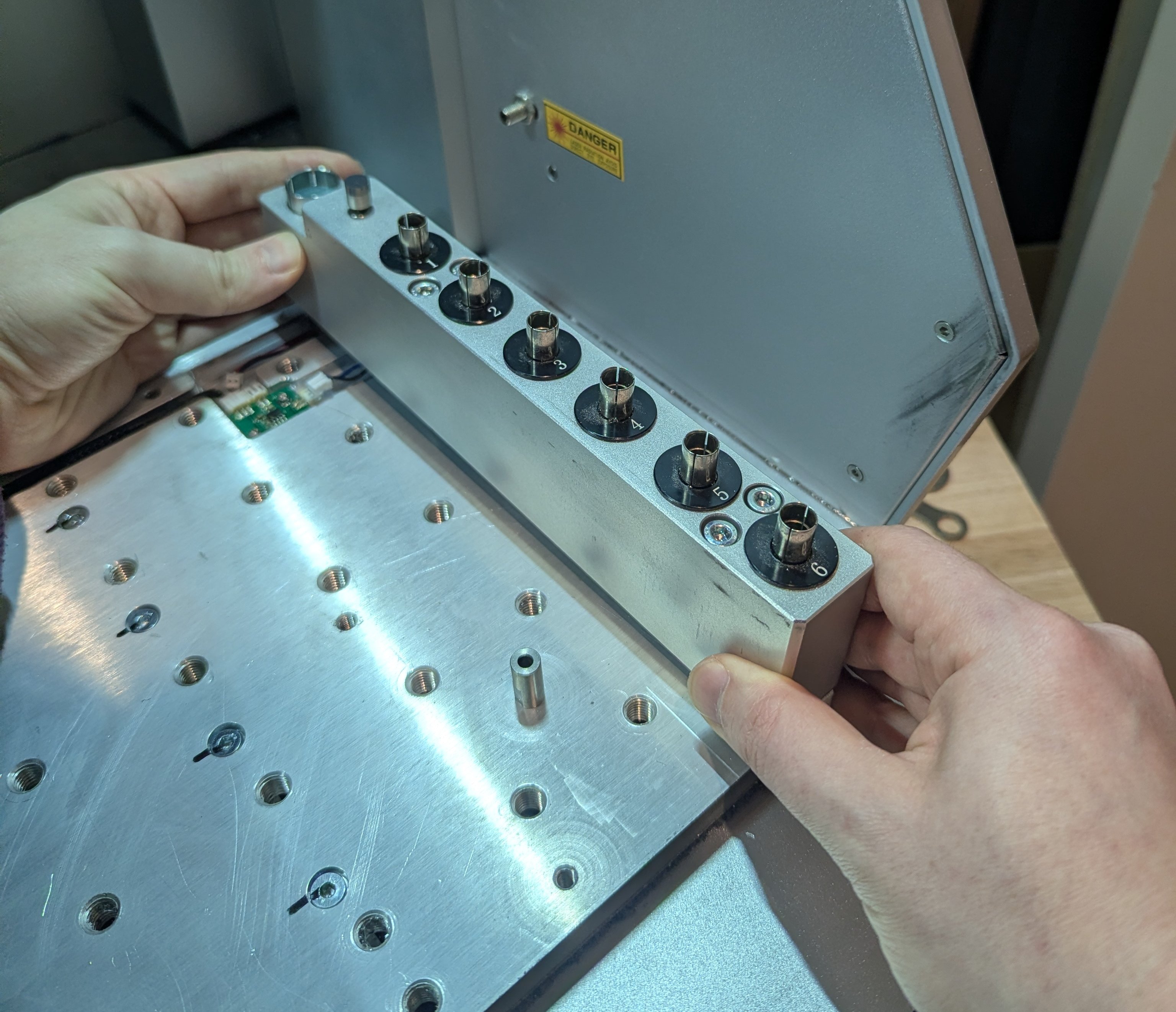
Remove original rack
3. Transfer the Tool Setter and Wireless Probe Holder to New Rack
- Use a 2mm allen key to remove the bolt on the side of the wireless probe holder, and remove the holder from the original rack. Be careful to not lose the small screw.
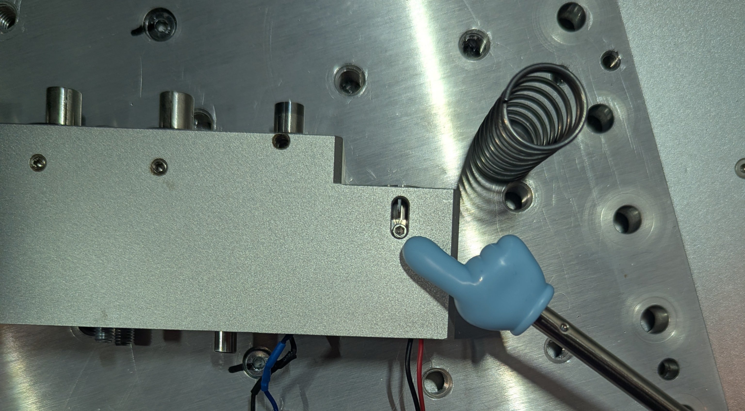
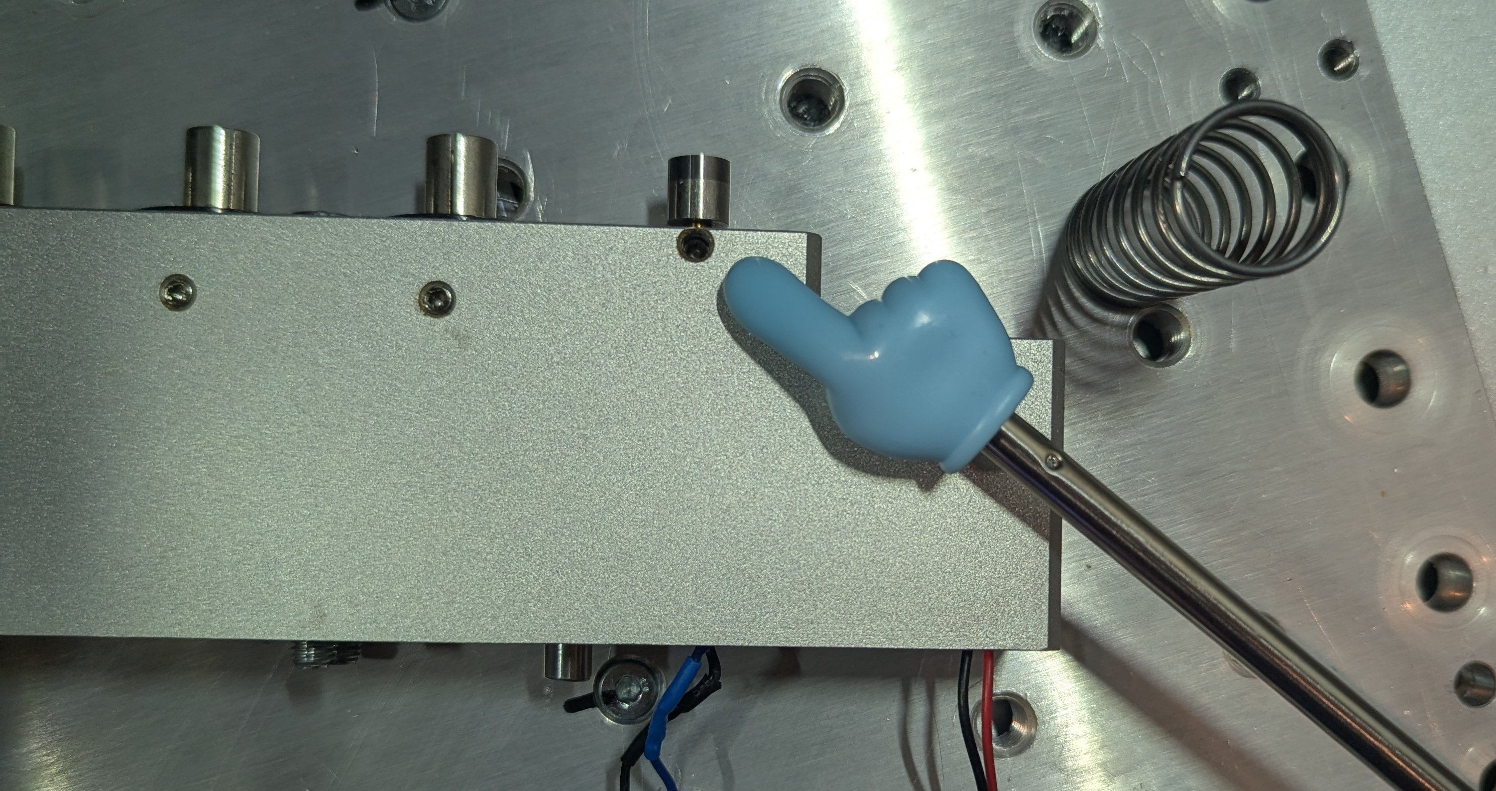
Remove wireless probe holder - Using a 2mm allen key loosen the set screw on the tool setter a few turns, and pull the tool setter out.
Remove the tool setter - You should now have the wireless probe holder, and tool setter removed from the original rack. Install them into their respective places in the new rack. Tighten the set screw, and reinstall the small screw on the wireless probe holder.
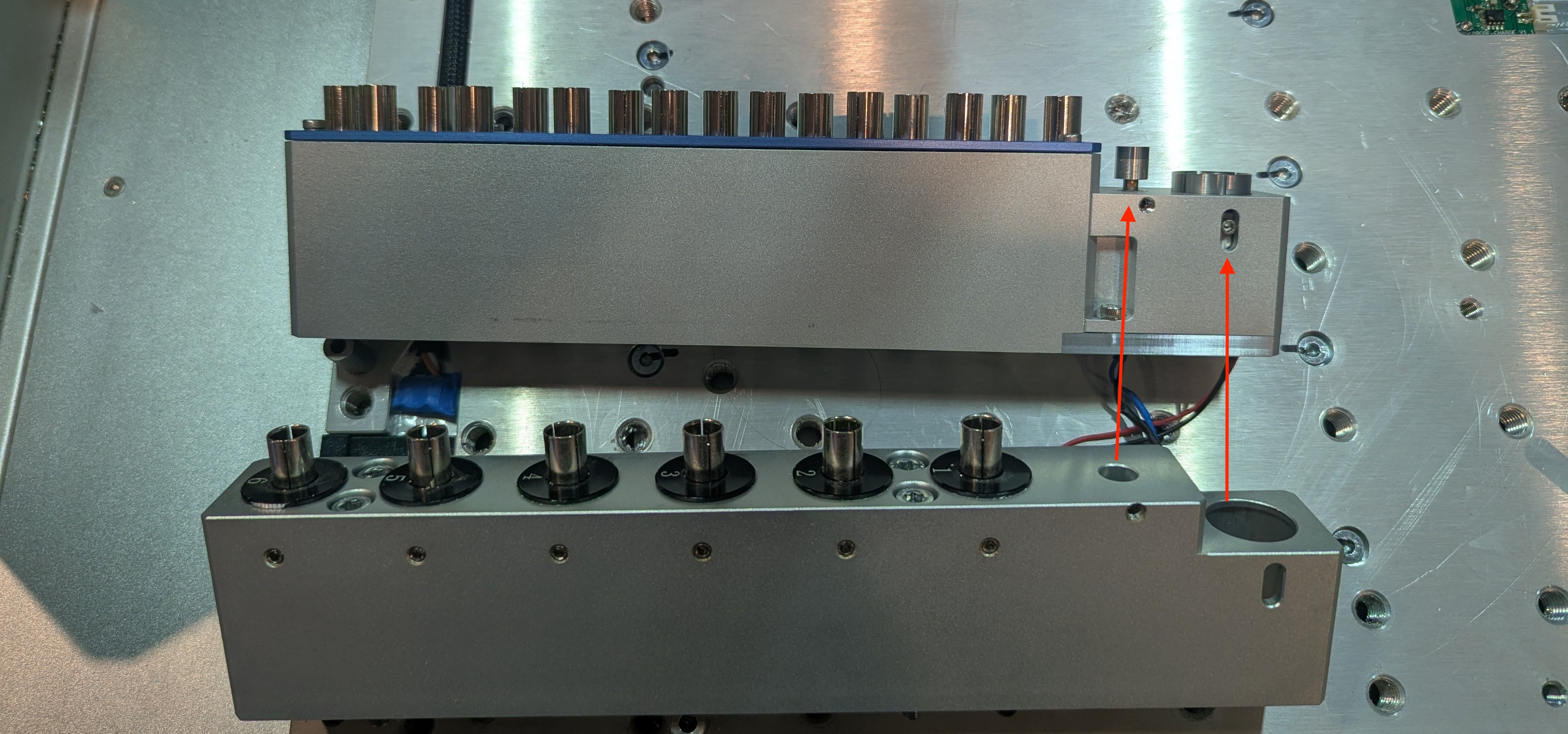
Transfer the tool setter and WP
4. Install new rack
- Insert the two included 6mm dowel pins into the back of the tool rack
- With the new rack on it’s side, plug in the tool setter and wireless probe cables.
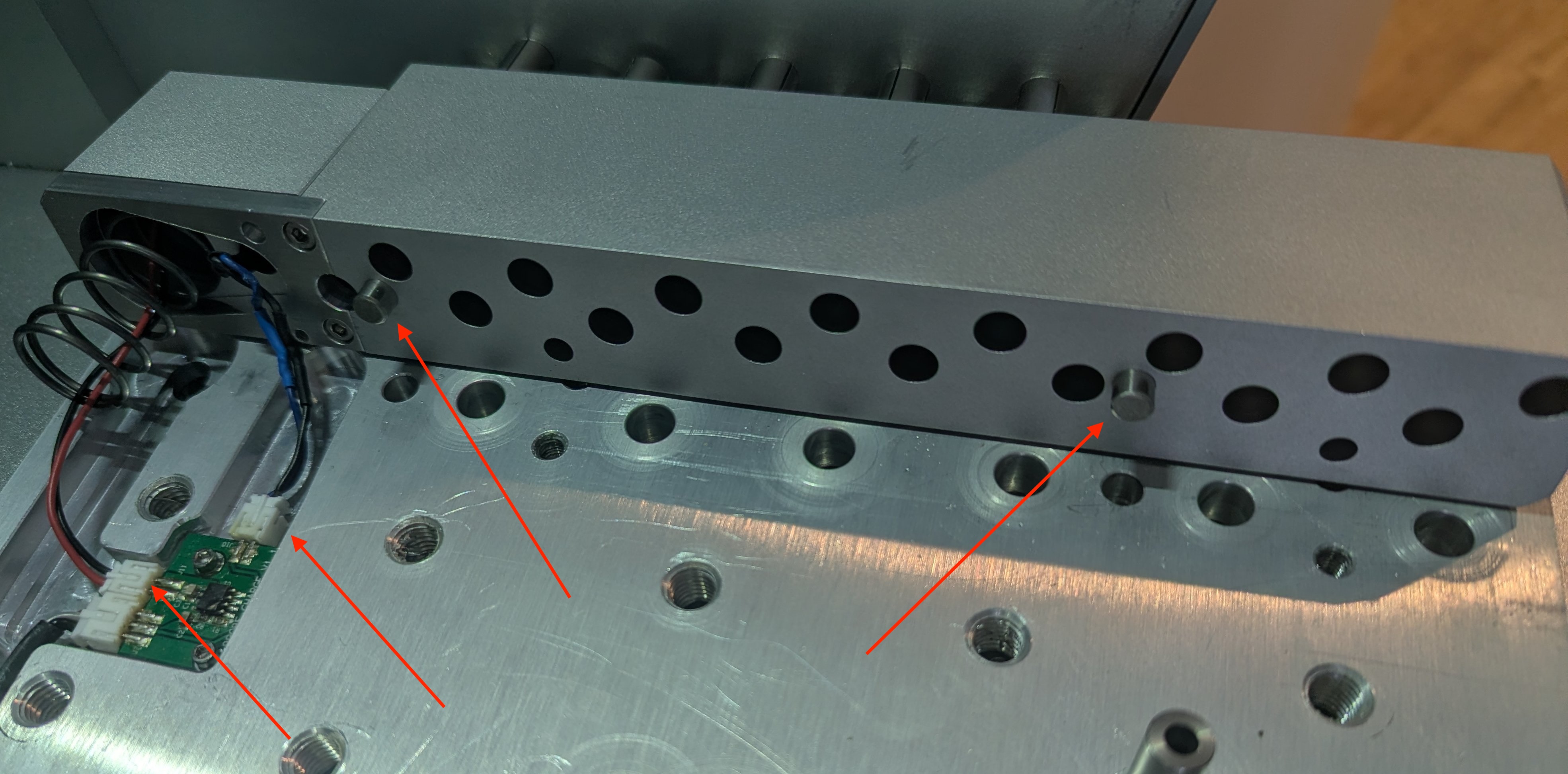
Insert 6mm dowel pins and connect cables - Use a 2.5mm allen key to remove the 5 machine screws holding the top cover on the new rack. Carefully remove the cover. If any of the tool grippers come out put them back into their slots
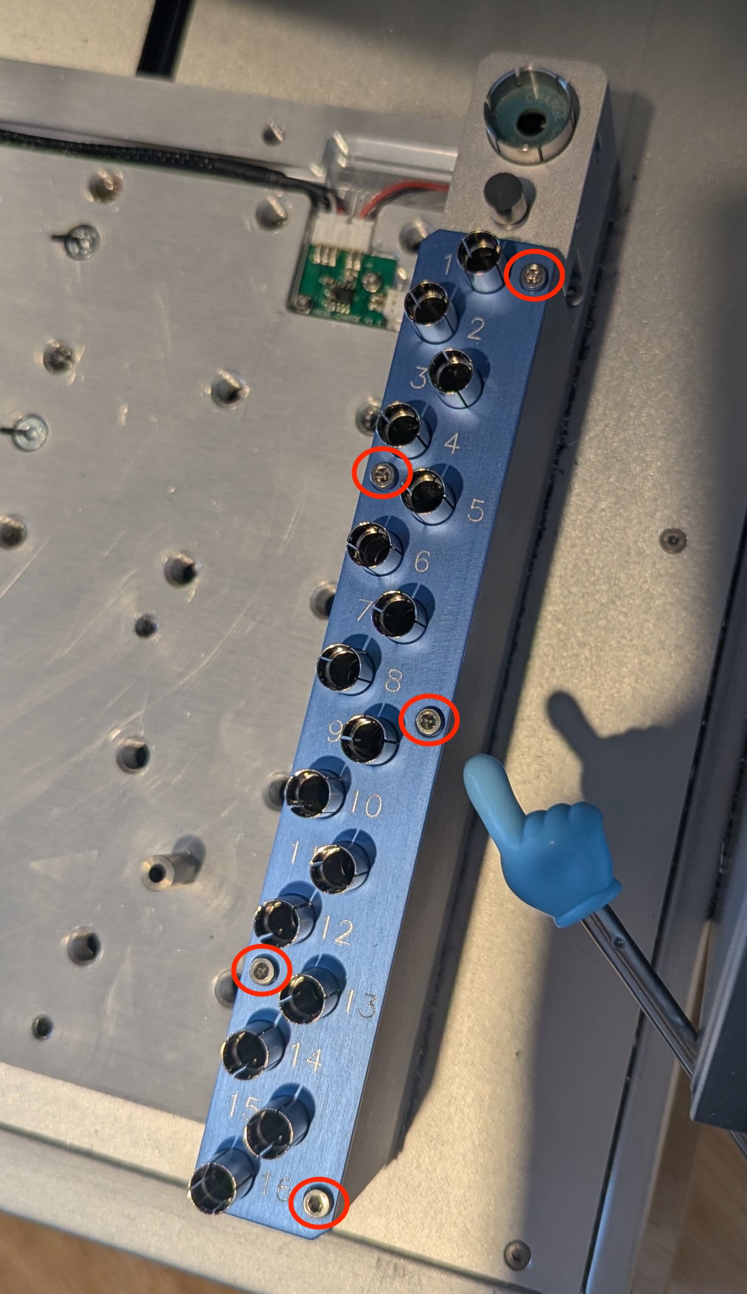
Remove 5 screws to remove the top cover - Use two of the large bolts from the original rack to bolt down the new rack. This uses the 4mm allen key. Due to the spring in the WP holder, I suggest holding the top of the rack down and securing the closest fastener first before the lower one.
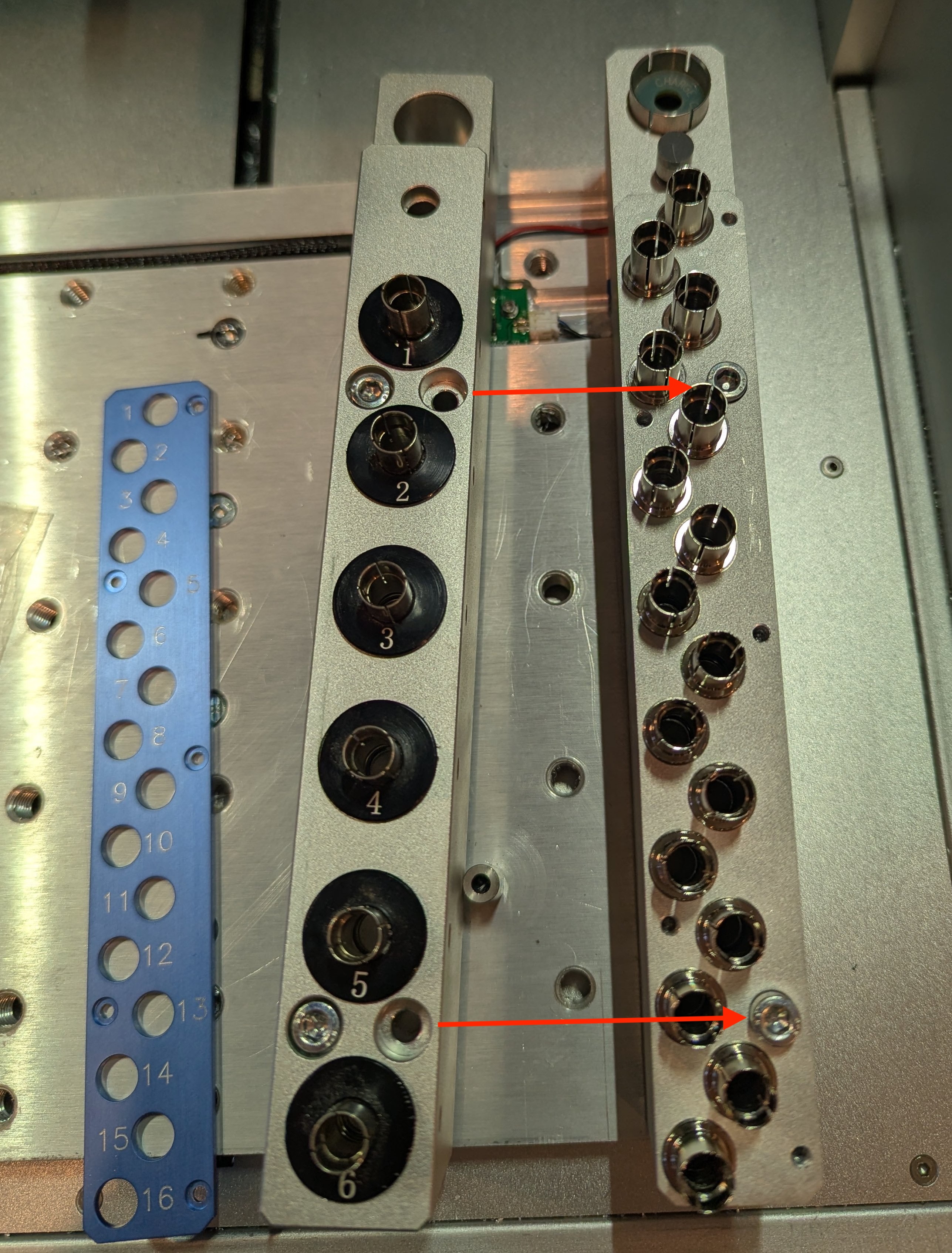
Bolt down the rack - Make sure that all the tool grippers are fully seated in their slots. If they are not, take the tool gripper out and push the spring into the recess for it.
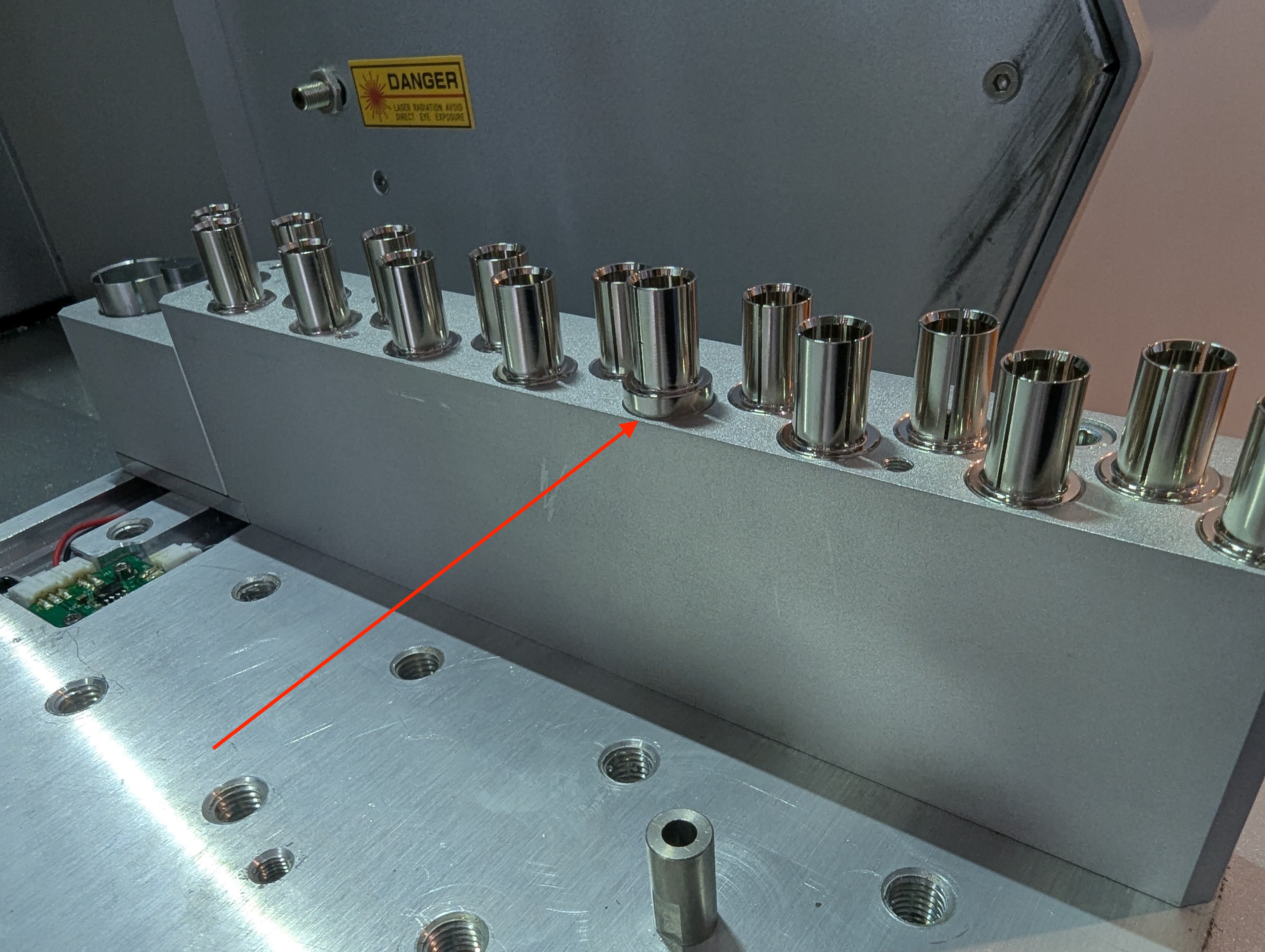
Example of a tool gripper not fully seated - Return the top cover and fasten it down with the 5 small machine screws removed during step 4c. Be careful to not overtighten, these are small diameter bolts in aluminium.
5. Reinstall bed
Return the bed back onto the carriage, and secure with the 9 bolts.
6. Configure Tool Setter Location
Run the following MDI commands to set the location of the tool setter on the rack:
config-set sd coordinate.probe_mcs_x -5
config-set sd coordinate.probe_mcs_y -45
config-set sd coordinate.reference_tool_mz -128.045
reset
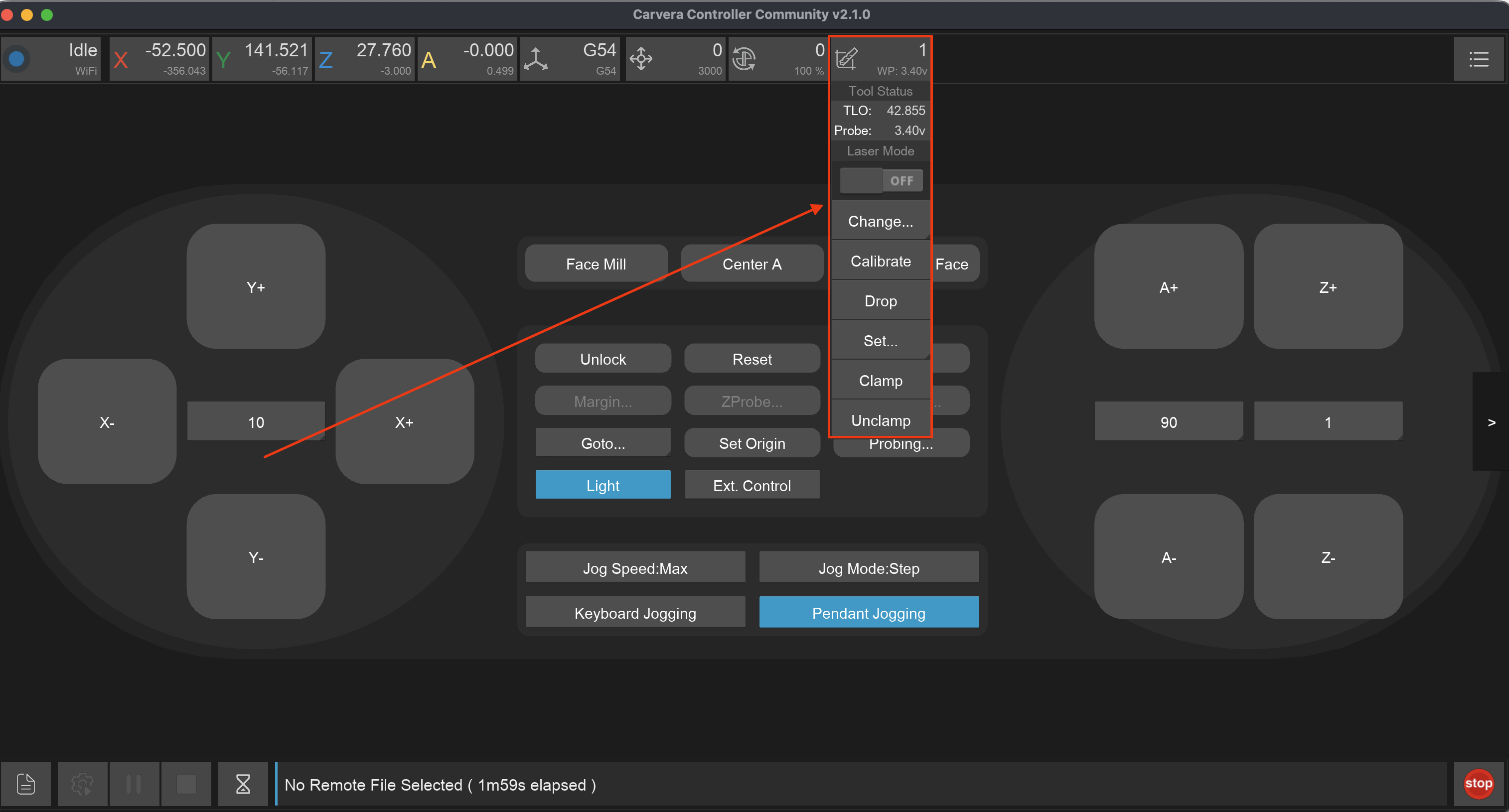
After the machine restarts the new tool setter location will be used. Run a tool  option from the TOOL dropdown menu
to check that it moves to the right location above the tool setter. Re run the commands with adjusted coordinates if necessary.
option from the TOOL dropdown menu
to check that it moves to the right location above the tool setter. Re run the commands with adjusted coordinates if necessary.
7. Configure Slot 1 Location
In order to be able to use the slots in the rack, their locations need to be configured. This can be done in one of two ways:
- By using the 3D Probe to locate the actual location of the slots - This is the recommended method
- By setting the expected location based on the settings used for the stock rack, then adjusting manually with trial and error
In both methods we first configure and test slot 1, and once slot 1 is perfect then we configure the rest.
If the slot definition is incorrect and it can bend the tool gripper out of shape and damage it. Be prepared to e-stop the machine if it looks incorrect.
8. Test Slot 1 and Adjust Z height
Test the Slot 1 configuration by inserting a tool into the spindle, setting it to tool 1, and dropping it. The tool should be dropped smoothly. See below as an example:
In the above example the tool is dropped into the slot correctly, but you will notice that the tool is not fully seated. Part of the collar is exposed above the tool slot. At no point was the tool lowered enough that the tool gripper was depressed. Ideally the tool should be dropped just low enough to push the tool gripper down a small amount. We can adjust this drop distance by changing the Z parameter of the slot configuration.
First we see the current slot configuration using M889 then we lower the Z value by a few mm using M890. For example:
M889
Tool Slots Configuration:
Tool 0: X=-4.960 Y=-24.980 Z=-114.400
Tool 1: X=-3.470 Y=-61.980 Z=-114.400
Tool 2: X=-4.960 Y=-114.980 Z=-114.400
Tool 3: X=-4.960 Y=-144.980 Z=-114.400
Tool 4: X=-4.960 Y=-174.980 Z=-114.400
Tool 5: X=-4.960 Y=-204.980 Z=-114.400
Tool 6: X=-4.960 Y=-234.980 Z=-114.400

; Lets lower it by 2mm
; -114.400 - 2 = -116.400
M890 T1 X-3.470 Y-61.980 Z-116.400
After lowering the Z, we retest again by dropping a tool. See how the tool was lowered just enough for the whole gripper to be pushed down a small amount when it released the tool, this is perfect.
If tool drops are not seating correctly like this, make small 0.1mm adjustments in the X/Y location using M889 until it does.
9. Configure the remaining slots
Now we will configure the remaining slots.
First we query the current slot config using
M890:M889 Tool Slots Configuration: Tool 0: X=-4.960 Y=-24.980 Z=-114.400 Tool 1: X=-3.470 Y=-61.980 Z=-116.400 Tool 2: X=-4.960 Y=-114.980 Z=-114.400 Tool 3: X=-4.960 Y=-144.980 Z=-114.400 Tool 4: X=-4.960 Y=-174.980 Z=-114.400 Tool 5: X=-4.960 Y=-204.980 Z=-114.400 Tool 6: X=-4.960 Y=-234.980 Z=-114.400To make configuration easier we will use variables. Set variable #101 to the value of the Slot 1 X position, #102 to the value of the Slot 1 Y position, #103 to the value of the Slot 1 Z position. Adjust the values in the commands below to match your slot 1 parameters.
#101 = -3.470
#102 = -61.980
#103 = -116.400
Run the below commands as-is to configure slots 2-16:
M890 T2 X[#101-7.87] Y[#102-12.036] Z[#103]
M890 T3 X#101 Y[#102-24.072] Z[#103]
M890 T4 X[#101-7.87] Y[#102-36.108] Z[#103]
M890 T5 X#101 Y[#102-48.144] Z[#103]
M890 T6 X[#101-7.87] Y[#102-60.18] Z[#103]
M890 T7 X#101 Y[#102-72.216] Z[#103]
M890 T8 X[#101-7.87] Y[#102-84.252] Z[#103]
M890 T9 X#101 Y[#102-96.288] Z[#103]
M890 T10 X[#101-7.87] Y[#102-108.324] Z[#103]
M890 T11 X#101 Y[#102-120.36] Z[#103]
M890 T12 X[#101-7.87] Y[#102-132.396] Z[#103]
M890 T13 X#101 Y[#102-144.432] Z[#103]
M890 T14 X[#101-7.87] Y[#102-156.468] Z[#103]
M890 T15 X#101 Y[#102-168.504] Z[#103]
M890 T16 X[#101-7.87] Y[#102-180.54] Z[#103]
Same as slot 1, test loading a tool and dropping into each of the slots. Adjust the slot config if required. Note to set the tools numbers above slot 6, you will need to use the Custom option in the TOOL dropdown

10. Configuring the Wireless Probe slot
The wireless probe slot (number 0) may also require some adjustment. While the Z value for the slot should be correct, the X and Y position might require some minor tweaking.
The slot is big enough that the 3D Probe is not able to locate it due to the machine travel limits. So the only way to set it is manually. The safest way to get the right slot location values is by getting the machine to pick up the probe with a slow feed.
Set the global feed override to move at 20% speed using the MDI command
$F S20. This will give you more time to e-stop the machine if the location is incorrectDrop/empty the collet so there are no tools inserted
Use the command
M6T0to attempt to pickup the probe. Be ready to push the e-stop button if the collet hits the top of the probe shaft. If the X/Y position needs adjustment it will look like this:Wireless Probe slot needs adjustment Same as before, query the current slot config using
M889and adjust the values usingM890. On my machine the right values were:M890 T0 X-3.960 Y-24.980 Z-112.Continue testing until the machine successfully picks up the Wireless Probe. If you cause a Halt and need to reset your machine, don’t forget to rerun
$F S20to slow down the movement speed.
11. Optional - Install Tool detector plastic backing
The tool occupancy sensor in the machine works with the High Capacity Tool Rack same as with the original rack. It can function without plastic backing, however if there is something on the bed that is reflective it will give a false positive that the slot is occupied. For this reason the step is optional, you don’t have to install the plastic backing but the machine works better with it.
Remove the red liner on the included plastic backing
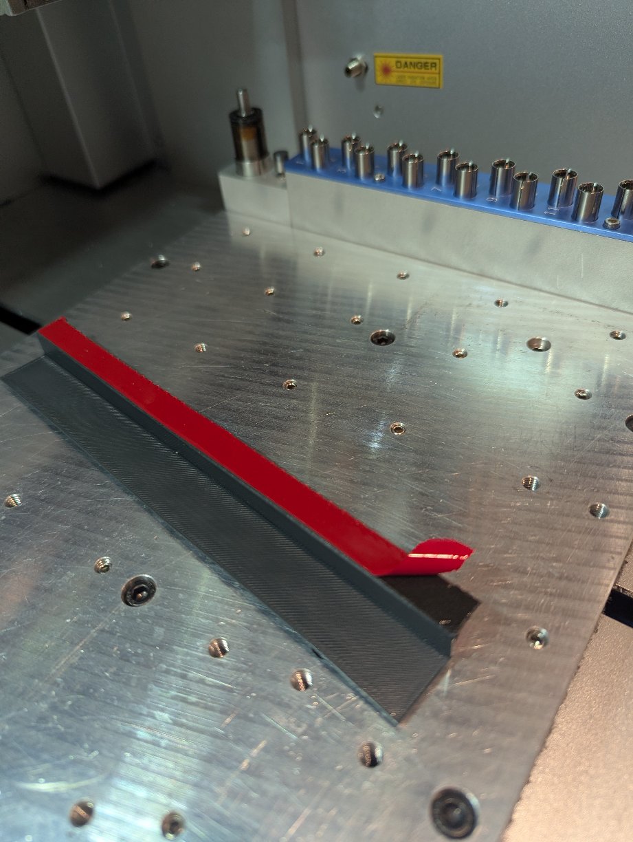
Remove red lining to expose the adhesive Press and hold the plastic backing against the tool rack. Hold it for 30 seconds for the adhesive to stick sufficiently.
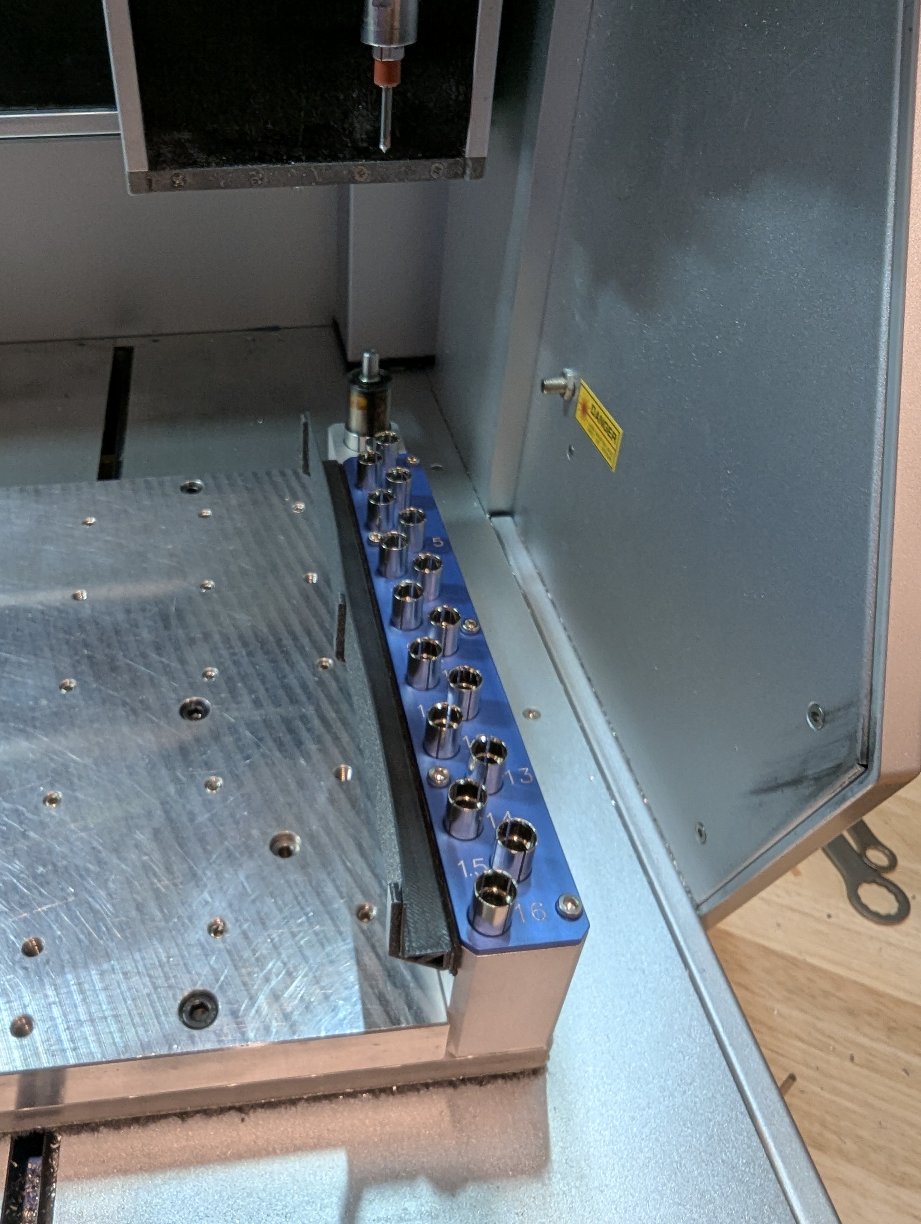
Press the backing against the rack
You are now ready to use the rack !